I had been intrigued by the QMAC HF-90 transceiver for a long time. A few years back, I finally was able to procure one second-hand on Ebay. It was said my unit came from the Australian Antarctic Division. I read somewhere that some 10000 units were made, mine has a serial number in the 6000 range and version 409 firmware. RXMP PCB revision on my unit is X.
In this post, I will explain how I converted the unit to “free tune” (vfo-style) operation making it much more suitable for amateur use. I have also added an SSB squelch.
IMPORTANT NOTES – READ FIRST
The conversion described here is not a beginner’s project. No PCB or kit is provided, and you will have to figure out several things (such as how to mount the Teensy in the HF-90 such that it fits) on your own. The conversion means soldering work needs to be done in the radio. Also, it is likely that after performing the conversion, the unit is no longer type approved. You have been warned.
Furthermore, the modifications I carried out are specific to my unit and PCB revision. I have no information on other / different PCB revisions, so if yours differs from mine, you will have to do some work.
All source code is provided under the GNU General Public License v3.0.
Retired and new functionality
Note that the following functionality is not available anymore after this conversion:
- Selcall receive & transmit
- Short tune pulse upon first transmit at a new frequency
- Frequency memories
- Reading the DMTF keypad (although adding that should be straightforward, there are a few pins left on the newly added MCU)
- Memory operation (although adding memories should be straightforward)
- PC programming
I have added the following functionality, not available on a standard HF-90:
- VFO style tuning, in selectable 25 Hz, 100 Hz, 1 kHz, 10 kHz, 100 kHz and 1 MHz increments over 2.0 MHz to 29.999 MHz
- SSB squelch
- Roger beep
- Menu selectable AGC and low/high power (although for some reason, low power does not work on my unit and results in no change in power output compared to high power)
- Zero-beat when pressing “tune” (no more 1 kHz tone which can cause interference to other users)
Introduction to the QMAC HF-90
When introduced, the QMAC HF-90 was certainly “disruptive” in the sense that it was a very small yet versatile HF radio, and with special firmware the unit could even do frequency hopping.
The HF-90 designer (and founder of QMAC electronics), Rod Macduff VK6MH has posted several very well made and very interesting videos explaining the ins and outs of the HF-90 design, which can be found here:
The design uses “contemporary” 1990’s / 2000’s era components and really was ahead of its time and done very cleverly with mass manufacture and ease of repair in mind. The use if cheap switching MOSFETs (IRF830) was another novelty, however due to their relatively large gate-source capacitance, power drops above approx 12 MHz, down to 5 W at 28 MHz. Later revisions included “dedicated” RF transistors to alleviate this issue. Mine has the IRF’s.
Schematics, placement diagrams (but not for the PCB bottom sides) and the technical manual are available on the web at: https://fccid.io/RK2HF90/Schematics/Schematics-373177
When I got my unit, it had seen its fair share of use, with a broken mic cord (which I replaced) but also some burnt out resistors in the PA feedback network (of which the technical manual mentions that these may blacken over time). I also replaced those, and was able to make radio contacts with it. The radio’s main drawback is the fact that it only offers channelized operation, VFO operation is not possible. Apart from that, I really disliked the audio quality and developed listening fatigue after a few minutes of use (more on that towards the end of this post).
Adding VFO (“free tune”) functionality
To add VFO functionality, the only option is to remove the existing microcontroller and replace it with another one. I opted for a Teensy 4.0 since I have done several other projects using this controller and one can use the Arduino IDE to develop the software. Furthermore, it allows using the audio library which I am going to use to implement a “smart” SSB squelch.
The Youtube video by VK6MH nicely explains the clever scheme employed by the dual PLL synthesizer, to arrive at small (25 Hz) frequency steps yet achieve good phase noise and fast locking performance, the latter is especially important for frequency hopping. Rod calls this a “magic number” scheme. Without going into too much detail (you really should watch Rod’s video!), the magic number scheme is about finding combinations of reference and feedback divider values which satisfy a certain tolerable frequency error, aiming for a phase comparison frequency within a certain optimal range. Too low a phase comparison frequency would yield a slow and sluggish loop response and require a complex loop filter to ensure good phase noise / reference spur performance.
The mixing scheme employed by the HF-90 is such that the first LO is tuned in 20 kHz steps, and the 2nd LO is tuned in 100 Hz (well, actually that turned out to be 25 Hz!) steps. The first IF SAW filter has a bandwidth of 30 kHz, allowing the first mixer to downconvert a “block” of 20 kHz, fine tuning is then accomplished by the 2nd LO which spans approximately 20 kHz.
The N and R divider values (the magic numbers) for both PLL’s for each frequency are stored in a Look Up Table. So, the quest for these magic numbers began. I developed a Python script to determine these numbers, taking into account the limitations of the MC145220 PLL chip with respect to the R and N divider values. The datasheet of the MC145220 is still available on the NXP website, and can be found here.
Mathematically, the N and R divider values need to satisfy the following conditions:

Where the Greek letter epsilon is the allowed frequency error (e.g. 25 Hz). The idea is that for any wanted LO frequency, there exists one or more (or so I thought, more on that later) combination(s) of an R and N divider value that yields a small but acceptable frequency error.
After a few hours of programming a Python script, I arrived at sensible results, here is a code snippet of the actual function to find the magic numbers:
def fast_find_magic_numbers(f, f_ref, fr_min, fr_max, allowed_error, maximize_fr = False):
    N_min = f / fr_max
    N_min_round = int(np.round(N_min) - 1)

    N_max = f / fr_min
    N_max_round = int(np.round(N_max) + 1)

    R_min = (N_min / f) * f_ref
    R_min_round = int(np.round(R_min) - 1)

    R_max = (N_max / f) * f_ref
    R_max_round = int(np.round(R_max) + 1)

    # limit R_max to the max MC145220 R division ratio of 8191
    if R_max_round > R_MAX:
        R_max_round = R_MAX

    N_range = range(N_min_round, N_max_round)

    if maximize_fr:
        R_range = range(R_min_round, R_max_round) # use for LO2  - start at a high F_r to minimize phase noise, also about 1kHz F_r does not seem to work?
    else:
        R_range = range(R_max_round, R_min_round, -1) # use for LO1 - start at a low F_r to prevent spurious locking

    f_r_range = [f_ref / item for item in R_range]

    f_actual = -1
    N_found = -1
    R_found = -1
    f_r_found = -1
    breakflag = False
    for f_r, R in zip(f_r_range, R_range):

        for N in N_range:

            if (abs(N * f_r - f) <= allowed_error):

                f_actual = N * f_r
                N_found = N
                R_found = R
                f_r_found = f_r
                breakflag = True
                break
        if breakflag:
            break

    return f_actual, N_found, R_found, f_r_found
Considering that the radio was designed in the ’90’s it was quite a feat at the time to figure out this synthesizer scheme! Kudos to Rod MacDuff VK6MH for getting that done.
It became apparent that some frequencies could never be generated with the chosen conditions. In particular, some frequencies very close to and on either side of 96 MHz (4x f_ref) on LO1, and some frequencies very close to and on either side of 83.612800 MHz as well as 83.625 MHz for LO2. So, I figured it would be good to verify the actual division ratios that the MCU sets especially for these “special” frequencies, by sniffing the SPI traffic on these lines.
Sniffing the SPI lines
The MC145220 chip has a serial (SPI-like) interface and since I had to figure out how to write to the PLL chip’s chip registers anyway, I used a logic analyzer and the brilliant Sigrok / Pulseview software to probe the SPI lines.
Pulseview has a great feature to include protocol decoders, and what’s even better, these decoders can be stacked. So, you can have an SPI decoder, and stack a chip-specific decoder on top of that such that you can directly view register contents. You can also write your own using Python. This is what I did, I wrote two decoders, one for the MC145220 registers and another one to decode the SPI traffic directed at the ten cascaded good ‘ole 74HC595 shift registers used to drive the LED display and control all radio settings. Writing these decoders turned out to be a straightforward task using the examples provided by Pulseview, allowing me to directly “see” the register values that the original MCU wrote.
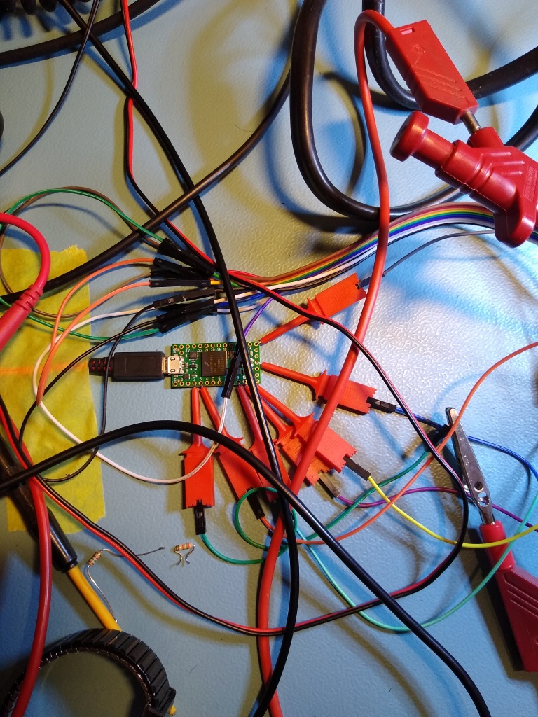
Probing the SPI lines with a logic was straightforward, I soldered wires to these lines at the location of the pullup resistors on the edge of the board:

The synthesizer and the 10 74HC595 shift registers in the HF-90 share the same clock and data lines. They have separate chip select lines (SEN and DEN respectively). Below is an example SPI transaction to the shift registers. Clearly 10 groups of 8 clock cycles can be seen.

The custom decoder, “stacked” on top of the SPI decoder, decodes this as follows:

Pulseview also allows to view the results in tabular form, which is more convenient, zoomed on the first few bytes:

And here is a capture of a synthesizer transaction:

The transaction is split into several groups:
- 2x a 1 byte transfer of the C (control) registers
- 1x a 2 byte transfer of the R (reference divider) register for LO2
- 1x a 3 byte transfer of the N (feedback divider) register for LO2
- 1x a 2 byte transfer of the R (reference divider) register for LO1
- 1x a 3 byte transfer of the N (feedback divider) register for LO1
The custom decoder, “stacked” on top of the SPI decoder, decodes this as follows:

In tabular form, note that the actual LO1 frequency can be directly calculated from the divider and prescaler ratios:
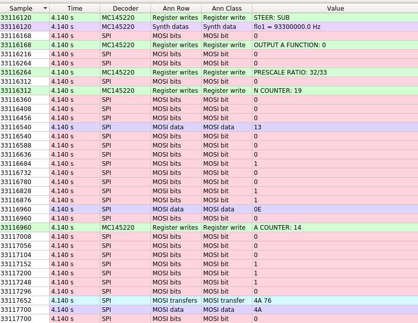
Having access to there registers, together with the HF-90 technical manual and MC145220 datasheet allowed complete reverse engineering of the SPI transfers.
Back to the magic numbers…
After checking these SPI sniffing results, it turned out that for these particular “difficult” frequencies, the lower limit of the phase comparison frequency is relaxed. This means that for these particular frequencies, lock time is slightly longer, but that can likely be accepted.
Based on Rod’s explanations, sniffing the SPI lines to the synthesizer for the “difficult” frequencies and after some experimentation I set the following conditions / fixed parameters for the calculations:
- LO1 frequency step = 20 kHz
- LO2 frequency step = 25 Hz
- LO1 allowed frequency error = 3 kHz
- LO1 Min phase comparison frequency = 40 kHz
- LO1 Min phase comparison frequency for “difficult” frequencies = 3 kHz
- LO1 Max phase comparison frequency = 202 kHz
- LO2 Min phase comparison frequency = 1 kHz
- LO2 Max phase comparison frequency = 14 kHz
The allowed error on LO1 is relatively large, but this can be nicely corrected by adding or subtracting a compensating offset on LO2, especially since the first IF SAW filter is 30 kHz wide and hence LO2 can span a larger range than 20 kHz. In addition, an offset on LO2 is set to compensate for the positive or negative 1400 Hz offset of the BFO frequency (depending on whether USB or LSB is selected). The BFO is divided down from 2 separate crystals in the 7 MHz range, one for each sideband.
For many frequencies, multiple valid solutions exist which satisfy the chosen conditions. I found through experimentation, that it is best to aim for a phase comparison frequency which is as high as possible on LO2, but as low as possible on LO1.
Putting it all together
Now that I had insight in how to write the synth registers, “cracked” the magic numbers, and also figured out what to write to the control shift registersI had all ingredients available to write custom software for the Teensy 4.0 MCU. So, I set off to develop an Arduino sketch. At a certain point, I was able to completely replicate the SPI transactions, so it was time to “pop out” the MCU with a PLCC44 removal tool, leaving an empty socket as can be seen below. In the below picture, the SPI sniff points can also clearly be seen.

I then hooked up the Teensy to these lines, note that I had to take care to remove the pull up resistors since the Teensy is not 5V tolerant, and all logic on the HF-90 runs at 5 V. Later, a 74HCT244 buffer was added to properly convert the Teensy logic levels to 5V, being HCT logic it has a logic high threshold of 2.0 V (at 5.0V supply voltage) which works reliably with the 3.3V logic high level out of the Teensy 4.0.
After a bit of programming, the software started to work, so I mounted the Teensy on a small PCB and managed to just fit it in the HF-90 by soldering the PCB onto the exposed pins of connectors PL3 and PL5. 5V is also tapped off from PL3. This PCB also houses the 74HCT244 buffer which is used as level shifter, and a MC41050 SPI controlled potentiometer which I use for volume control instead of the DAC0800.

Teensy pinout is as follows (note that this can probably be optimized, it grew “organically” 🙂 )
Encoder and keypad signals are broken out from the PL1 and PL2 connector which connects the front panel to the RXMP and PASW PCB’s. For PTT, I cut the PTT pin on PL2 to break the signal into a PTT in (from the front panel) and a PTT out (to the RXMP/PASW boards). I then epoxied the pin that goes into the front panel to ensure it remains mated.
| HF90 Signal Name | Signal description | Direction | Type | Teensy pin number | Teensy pin name | Remarks |
| SEN | Synth Enable | OUTPUT | Digital | 10 | CS | Through 74HCT244 buffer |
| SCK | Serial Clock | OUTPUT | Digital | 13 | SCK | Through 74HCT244 buffer |
| DEN | Display Enable | OUTPUT | Digital | 9 | 9 | Through 74HCT244 buffer |
| DOR | Serial Data | OUTPUT | Digital | 11 | MOSI | Through 74HCT244 buffer |
| VEN | Volume pot enable | OUTPUT | Digital | 8 | 8 | Through 74HCT244 buffer |
| QUAD1 | Quadrature encoder 1 | INPUT | Digital | 2 | 2 | Needs internal pullup |
| QUAD2 | Quadrature encoder 2 | INPUT | Digital | 3 | 3 | Needs internal pullup |
| PTT_OUT | Push to talk output | OUTPUT | Digital | 5 | 5 | Through 74HCT244 buffer, active low |
| PTT_IN | Push to talk input | INPUT | Digital | 4 | 4 | Through series 1N4148 diode, active low |
| Audio in | Audio input | INPUT | Analog | 16 | A2 | For squelch |
| BR | Bottom row | OUTPUT | Digital | 6 | 6 | PWM tone output and keypad scan output |
| TR | Top row | OUTPUT | Digital | 7 | 7 | PWM tone output and keypad scan output |
| LCL | Left column | INPUT | Digital | 20 | 20 | Keypad |
| MCL | Middle column | INPUT | Digital | 21 | 21 | Keypad |
| RCL | Right column | INPUT | Digital | 19 | 19 | Keypad |
An additional thing worth mentioning is that with this conversion, the lithium battery backed RAM is no longer in use.
He’re is a video showing the free tune functionality in use:
Now that the radio is a lot more user friendly, let’s look at some other improvements.
Distortion in the 455 kHz IF and AGC improvement
When looking at the schematics which can be found here, the 455 kHz circuitry on the RXMP board contains two anti-parallel diodes just before the 455 kHz signal from the IF amplifier chain goes into the product detector (a good ‘ole LM1496).
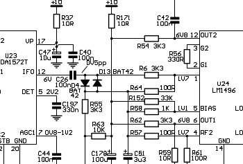
When attaching a scope over these diodes while feeding the radio with a CW signal such that there is a tone at 455 kHz, distortion could clearly be observed. After removing these diodes, the radio already sounded much better. BUT, upon strong signals it became apparent that the AGC attack time was too long! This resulted in a loud “CRACK” for about 50 msec everytime a strong signal would be received. I suspect that the diodes were used to mitigate this issue, but I wanted to address the fundamental issue of the AGC attack time being too long. The AGC circuit is cleverly built around the TDA1572T “all in a chip” AM receiver. The Technical manual mentions that this is a hang AGC, but I could not figure out how it would actually hang. Instead, a comparator is used which senses whether the AGC is in the “attack” or “decay” mode, depending on the voltage difference over a 33 Ohm resistor in series with the AGC line of the TDA1572 and the switchable (AGC fast/slow) electrolytic capacitors. When in “attack”, the comparator “trips” leading to Q11 conducting which fast charges the electrolytic capacitors. Well not exactly fast as the 1 MOhm series resistor limits the amount of base current (and, through the hfe of the transistor) the collector current. So, I reduced this resistor to 1.5 kOhm and then the issue was mostly gone, with good AGC behaviour! I also put a 3k9 resistor in parallel with C44 to improve AGC response further.
Below is a table that lists all modifications I made.
| Action | Refdes | New value | Remarks |
| Removed | D3, D14 | To eliminate 455 kHz clipping distortion | |
| Removed | C128 | To disable volume DAC | |
| Removed | C39 | To disable volume DAC | |
| Removed | R132 | To reduce noise coupling in from supply (although I am not using this opamp anymore) | |
| Removed | R12, R13, R14, R17 | Pull up resistors on SPI databus (could have left these in place in hindsight) | |
| Added parallel 3k9 | C44 | 3k9 | For less “flat” AGC response |
| Replaced | R65 | 1k5 | For faster AGC response |
| Removed | C217 | To eliminate TR/BR audio input on receive and associated noise (this capacitor was on the RXMP bottom side) | |
| Removed | C189 | To eliminate key trigger on DTMF input |
SSB squelch algorithm
I have been looking for a good “syllabic” SSB squelch system for years, but apart from some old hardware implementations (such as the one described by the two “Collins” Gurus Sabin & Schoenike in this book, I have not found other implementations. Until Pieter-Tjerk PA3FWM had included a new squelch algorithm for the websdr, and published details of his algorithm here. This algorithm works very well, and is independent of absolute power level, it only depends on SNR. I have taken the idea of his algorithm, and included it in the code. It makes use of the excellent Teensy audio library.
Here’s an excerpt of the source code up to the point where it determines whether the relative variance of a signal exceeds the threshold:
// Frequency domain relative variance squelch for SSB/CW, invented by PA3FWM: https://www.pa3fwm.nl/technotes/tn16f.html
    float sum;
    float mean;
    float variance;
    float relvar;
    uint8_t i;

    if (myFFT.available()) {
      // each time new FFT data is available

      // calculate the mean of the data
      sum = 0;

      n_bins = high_idx - low_idx + 1; // the number of bins to be processed in the FFT for a 1024 point FFT
      for (i = low_idx; i <= high_idx; i++) {
          sum += myFFT.read(i); // sum over all bins in the FFT
      }
      mean = sum / float(n_bins); // divide the sum by the number of datapoints

      // calculate the sum of the squares of the differences from the mean
      sum = 0; // re-initialize sum
      for (i = low_idx; i <= high_idx; i++) {
          sum += pow((mean - myFFT.read(i)), 2); // sum over all bins in the FFT
      }

      // from that, calculate the variance
      variance = sum / float(n_bins); // divide the sum by the number of datapoints

      // now calculate the relative variance by dividing the variance by the mean squared
      relvar = variance / (mean * mean);


        if (relvar > thresh) {
// Now there is a signal
The squelch works very well, as can be seen in this video:
Roger beep
I have also added a roger beep (actually, a Quindar tone). Originally, I had set this to 2475 Hz, but noticed that the transmit audio response already rolls off quite a bit. So, to preserve the character of the tone, I now use half this frequency at 1238 Hz. Duration of the tone is 250 msec, just like the Quindar tones. It can be switched on and off through a menu.
Git repository
I have published source code for the Teensy sketch and the Python scripts to calculate the magic numbers and the Look Up Tables on Github here under the GNU GPL v3.0 license.
Buy me a coffee!
I am a fan of (good!) coffee. If you like this project and would like to convert your HF-90 as well, then I would really appreciate if you buy me a coffee at: https://www.buymeacoffee.com/pe4wj
Credits
I’d like to thank the following people:
- Ben Buxton for his great rotary encoder library
- Pieter-Tjerk de Boer PA3FWM for inventing the relative variance squelch algorithm
- Paul Stoffregen and everyone involved in the Teensy Audio project for creating such great pieces of hardware and software
- Rod MacDuff VK6MH for creating a great bit of kit and his splendid videos explaining the HF-90 design

Hi – thank you for this project: I think!
Looks fascinating.
Can you tell me where the volume ‘control’ now resides? I see you using the CHAN up and down buttons to toggle the bandwidth for tuning, and the MODE button to toggle through power level, etc but wasn’t sure about Volume. I’m guessing volume is now using the CLAR up and down buttons?
Also can I confirm the TUNE button will still operate in the normal way?
Thanks again a great analysis.
Cheers
Steve VK2LW
LikeLike
Hi Steve,
Thanks!
Indeed, I am now using the CLAR up/down buttons for setting the volume. But, I might change this later as I am pondering over how to add frequency memories.
Furthermore, I can confirm that the TUNE button still operates in the normal way, except for that the radio now off-tunes by 1 kHz to ensure that the 1kHz tune tone is actually zero-beat while tuning, so as to not cause QRM to other users of the channel. After the tuning cycle, the radio turns back to the actual operating frequency.
73,
Wouter Jan PE4WJ
LikeLike
Hi Wouter Jan Thanks for getting back to me.
While I’m reasonably competent with solid state repairs (and to a lesser extent ‘hollow-state’) I’ve not played with the Arduinos. Been tempted, but not this far.
Would really like to tackle this project however I’m worried about the steep learning curve!
My HF-90 set-up is pretty good. I have the manual tuner (auto just way too expensive), backpack plus several QMAC antennas, incl the vertical. I run it off a 15Ah LiFePO4 battery with 45 W fold-out solar panel and an MPPT controller.
The free-running VFO would make it even better again.
Appreciate your incredible work on this project.
Cheers Steve VK2LW
Sent from my iPhone
>
LikeLike